Building a DIY single-loop MIDI switcher
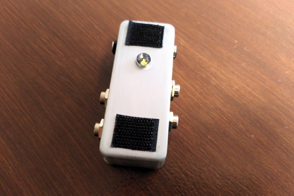
Here's the "Loop1", a single-loop MIDI switching box I built. :-)
It is a compact true-bypass loop switching pedal controllable via MIDI. It is essentially an Imp-3PDT from Oscillator Devices boxed into a 1590A enclosure.
For download links, see the build page for the Loop1.
I built this because I sometimes fall one loop short on my 4-loop MIDI loop switcher (also an Oscillator Devices gizmo, the HYDRA4). Instead of finding a new, larger switcher, I thought a single-loop MIDI switching module I could add or remove from my board depending on the needs would be handy. The only commercial offering I found was the One Control MIDI Solo. But it is stereo (which comes with a price tag) and has a bulky 5-pin DIN connector -- I prefer the more compact mini-MIDI way which uses 3.5mm TRS connectors. Also going DIY is fun, so here I am!
Circuit schematic
Here's a schematic I put together with KiCAD:

The Loop1 is basically a MIDI-controllable 3PDT bypass: when off, the Imp-3PDT connects JI and JO, so Input goes straight to the Output. When enabled, the Imp-3PDT connects JI to FI, and FO to JO. So Input goes to Send, and Return goes to Output.
Since the true-bypass switching functionality is provided by the Imp-3PDT, this project basically amounts to a fair bit of off-board wiring.
Aside from the audio jack pins, we must connect the +9V/GND pins of the Imp-3PDT to the DC jack, and its MIDI Sig/Ref pins to the MIDI jack. Following the Type-A MIDI-over-TRS standard, Sig goes to Tip, and Ring goes to Ref (I remember it like because "Ring" and "Ref" both have an "R").
As I suck at point-to-point wiring, I wired the LED and CLR on a tiny veroboard for easier relay of 9V from the DC jack to both the CLR and the Imp-3PDT.
Build model
I like to draw a full-size model in Inkscape to place drilling holes and make sure everything will fit inside the enclosure.
The Loop1 is no exception, especially given the amount of jacks and the use of the infamous 1590A. Its external dimensions are only 90mm long, 38mm wide and 30mm high!

The jacks are placed at the bottom in an alternating fashion. Then I put the LED over them. The Imp-3PDT is on a wall between the Send/Output jacks and the DC jack, and the MIDI TRS jack goes on the other side.
Quite tight but there was still some margin for error and room for finally assembly inside the enclosure.
Also you can see how closed jacks wouldn't have fit, and how "standard" Alpha-type open jacks would have been much tighter. There is still a 21.5mm spacing between the audio jack ports. This means regular "pancake" patch cables will fit side to side (I represented them by the dotted blue circles on the drawing).
Enclosure drilling
The Inkscape file has a "Drilling template" layer with only the box layout and hole markings. Before drilling, I apply masking tape to the enclosure. Then I print the drilling template in real size, cut it to shape and tape it onto the enclosure, making sure to align the edges.
As for the actual drilling, first mark the holes with a punch and a hammer to prevent drill wandering. Then what I do is drill all the holes with a 4mm HSS drill bit. Only then I widen the holes to the required size with a step drill. The audio jacks required 10mm, and the LED bezel, MIDI jack and DC jack require 8mm. (Depending on your components of choice this may vary.)
Assembly
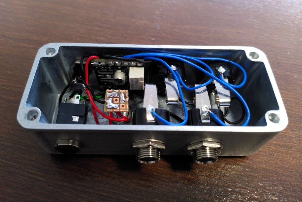
Here goes the final wiring and assembly. I first soldered wires on all the ports of the Imp-3PDT, then mounted it onto the wall with velcro.
Then I prepared the LED veroboard, connecting the +9V and LED wires from the Imp-3PDT, and a third wire for the DC jack +9V. A third-hand tool was especially handy to hold the veroboard above the enclosure and keep the wire lengths reasonable.
I then mounted the LED onto the bezel, then the DC jack, and soldered the +9V wire from the LED vero to it.
Next came the ground wires. I soldered a single GND line going from the DC jack and circling through all the audio jack GND pins up to the Imp-3PDT.
With that done, I mounted the audio jacks GND pin down so that the signal pin is facing up. I connected the blue signal jacks from the Imp-3PDT to the jacks one by one, bending them in a uniform way for a fairly clean look.
The last step was the 3.5mm MIDI jack. I mounted it in the enclosure, then soldered the two wires from the Imp-3PDT to it, twisting them together for better looks. Green is Ref which goes to Ring (again, I remember with the R's), and black is Sig which goes to Tip, as per the type-A standard for MIDI over TRS.
That's it!
Possible enhancements
This module works great as it is! It can toggle the loop on or off by sending MIDI CC messages with my MIDI controller. I used the Loop1 to make a DIY delay pedal MIDI-switchable. I was eventually able to move it to a loop of the HYDRA4, but if I'll have the Loop1 handy if I ever need an extra MIDI-switchable loop on my board again.
There are only two things I would improve.
First would be soldering a mini push-button to the Imp-3PDT. Then I'd have easier access to the functionality designed to be activated via an SPST switch soldered to the mounting pads I left unused. In particular setting the MIDI channel without MIDI CC requires me to short those pads manually for now.
Second thing is labelling the audio ports. Right now I remember the layout but at least labelling with the letters I, S, R and O would be better. I have some black StazOn solvent ink and alphabetical stamps I could use. Stamping gives a very definite DIY look as it's very hard to perfectly align the letters on entire words. But for single letters it could look nice enough.
Wrap up
Here were my design notes about the Loop1.
You can find download links for the design files (wiring diagram, Inkscape model) on the build page for the Loop1.